Friday 6 December 2013

Arduino Starter Kit - Chapter 11 and 12


I'm sorry, I cannot keep some scheduled post method, I post when I can.
Today I'll explain the chapter 11 and 12 of the Arduino Starter Kit

11 CRYSTAL BALL a mystical tour to answer all your tough question
12 KNOCK LOCK tap out the secret code to open the door

Chapter 11:
In this project we'll use an LCD screen, that can be used to display alphanumeric characters.


In the code section they explain how to use the switch case statement and the random() function.
The switch() statement execute different code depending on the value you give it in input.
Each of these code is called case.
Syntax:

switch (controllVariable){
     case 1:
     //..
     case 2:
     //..
     case N:
     //...
}

The random() function returns a number based on the argument you provide it.

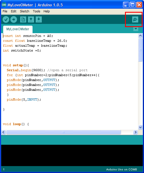
I really wanted to do some modification to this project, or also create some project by myself with the lcd screen, but this time the problem is pretty physical: as you can see in the opening pic the breadboard is pretty full, and sadly I do not own a bigger one. When I can afford to buy some more pieces I post an update.


Chapter 12:
In this chapter we'll going to use the piezo as input: When plugged into 5V, the piezo can detect vibration, that can be read by the Arduino's analog input.


In the code section this time they introduce how to declare you own function. When you declare your own function you must indicate if it going to return value or not, in the first case you must indicate the type (int, long, float, etc...) otherwise you indicate the type as void, I.E. like you see in the basic function setup() and loop().
Next you indicate the name of the function and after that, inside round bracket, indicate the argument of the function.
Syntax:
[type/void] functionName (argtype arg) {
//..
}

Here a video demonstration of this project:


Next time I'll post all the three remaining chapter, and then I finally concluded the Starter Kit and so I can finally try something that run on my mind from some time.

Ygy Freezone

Tuesday 26 November 2013

Internet of Things and the world of tomorrow


No matter where you are, everyone is always connected


The introduction line above here, is an aphorism from an old (1998) anime called Serial Experiment Lain, in this anime everything and everyone are always connected to the net and the story plot run both on the physical and the virtual world. This anime was broadcast 15 year ago, one year before Matrix, but some year after the cyberpunk revolution of the 80's. 
All of these things are pioneer of the idea of the Internet of Things (IoT) which is the current technological trends for the coming years: from the 80's we imagine a world full connected to the net, physical and virtual world connected into a new way of existence.
But what is this IoT things? IoT , according to the wikipedia definition, is a concept born in the 1999 from the mind of Kevin Ashton and refers to the virtual representation of some real object and their connection on the net. Using some tag, like RFID/NFC chip or even a simple qr-code, the object can be referred to it's virtual entity. 
Imagine: you go into a shop in your preferred mall and see some dress you like, with your AR-glasses watch and select the object and put it into a virtual shopping cart. 
Then you move near the mirror, put your phone (which is connected with your glasses) into the right place on the mirror and your cart will appear on the mirror glass, then you can choose something there is in your cart and virtual try on yourself.


Then when your are done you simply put your phone on the register, doing this you just do the self checkout, empty your cart and print the bill, when required you pay all what you buy simply putting your phone on the contact less card reader. After paying  your order, go out from the shop, and see the street of the mall, on your lenses appear all the information needed from every shop...


... On the metro on the way back home, you check the temp in your house and set ON the heating system, during the trip you remember that you want to cook some chicken tonight, so you turn ON the oven from your smartphone. Meanwhile your cleaning robot send you an notification that he has done his work, and while wait for new task he go to the recharger point...


For some of you these situation seems like something from an Sci-Fi movie, but in fact this is more near to us than you can expect: nfc payment from your phone is already real in some country (like USA and UK for example), the Google Glasses are near to the official release (the rumors say that they release the G-Glass during the 2014) and other similar device are in the home straight, there is some app for our smartphone which give a real Augmented Reality experience and domotic is already a reality in some nation.
Cisco System expect that before the 2020 there will be more than 30 billion device connected to the internet, not only smartphone or tablet or computer, but everything can have it's virtual counterpart, and at that moment the IoT change is name to Internet of Everything. We will be surrounded by computer and connection, the virtual world will be inseparable from the physical world and vice versa.

I read and hear lot of speeches, from the internet and from my CEO, and when I hear one of them reduce this digital revolution to one single stage make me sad. 
There is no way to separate electronic engineering from software engineering at this point, if you want to be remembered as innovator you can't simply follow the flow doing some app for a smartphone. You must create your system and your app must be integrated in your system.
When I proposed to do some workshop on the microcontroller platform for electrical prototyping, like Arduino, to the technical leader of my company, who has always been enthusiastic in this IoT stuff, he answered me "but why do we need this?". He simply do not get the point of these time, he simply follow the flow. This is not planning the work for the next year, this is a try to stay afloat against all the competitor.
If you want to be in the revolution you must be the leader of the revolution: In or Out, there is no half term.

We as software developers, designers, analysts, as electronic and telecommunications engineer for the first time in history, really have the future in our hand. We can shape the future, in the way we want.
We can finally create the Future that we are ever dream, but we are ready to shape it?

Ygy Freezone

Thursday 21 November 2013

Arduino Starter Kit - Chapter 09 and 10


It's been a long time since my last post, I'm sorry I've be very busy in these weeks.
Trying to restart the Arduino Starter Kit explanation, today I'll explain what you can find in the chapter 9 and 10 of the manual.

09 MOTORIZED PINWHEEL a color wheel that will have your head spinning
10 ZOETROPE create a mechanical animation you can play forward or reverse

Both of this chapter do not add anything new to the code side, in fact both project are pretty similar to the code used for turning on a led.

Chapter 09:
In this chapter we'll use a motor, a mosfet and a diode.

Motors typically require more current than the Arduino can provide. The Arduino can only provide 40mA from it's digital pins, much less than required to a motor to work.
So we'll use an external 9v battery.

A  mosfet is a transistor, and they are components that allow you to controll high current or voltage power sources from the current output of the Arduino. A transistor is in fact a digital switch: when you provide voltage to the gate pin it close the circuit between the other two pins (source and drain).

A motor is a type of inductive device. Induction is a process by which a changing electrical current in a wire can generate a changing magnetic field around the wire. When a motor is given electricity a tightly wound coil create a magnetic field which cause the shaft to spin around.

To protect the transistor from the back-voltage generated from the inertia of the motor you should put a diode in parallel with the motor. The diode allow electricity to flow in one direction protecting the rest of the circuit.


Chapter 10:
Based on the previous chapter, here you use an H-Bridge to reverse the polarity of the motor.
An H-Bridge is a type of component know as Integrated Circuit that has a lot of transistor built in.


Since there is no new code to explain in both chapter for today is over, hope to post the next chapter a little earlier than the last time.

Ygy Freezone

Wednesday 6 November 2013

Java Application for tracking monthly income and balance pt3


Ok, ok I said I'd post the next chapter of the Arduino Starter Kit, but I can't leave this project in half with horrible layout and various fix to do, so here we are.

I fix the layout, improve the readability and add the message box when closing.
For fixing the layout I choose to separate the components into 3 JPanel, adding all three into a GroupLayout set as layoutmanager of the JFrame

The first and the third JPanel are themeselves managed with a GroupLayout, otherwise the second JPanel has a simple FlowLayout because in it there is only the JTable.

The graphical result is the screen down here:


The only fix I need now is to align the third JPanel to center, or move the JCheckBox and the save JButton near the extreme left, aligned with the left edge of the JTable.


To add the message in the closing action when have unsaved modification, I inherit the WindowListener and in his windowClosing() method I managed the Exit. For doing this you must set the default closing action of the JFrame to DO_NOTHING_ON_CLOSE , and change when it need.
I don't have really implemented the others methods because I don't need them in this project. But I must put their implementation in my code or there is a compiler error caused by the not fully implementation of the methods present in the WindowListener interface.

If you want to see the full code is still on my GitHub repository . Now, as you can see up here, I need to align the JPanel3 to center, and change the JLabel jlabError with a JOptionPane message, and maybe improve readability and shortening the code, but these are minor improvement so next evening I can work on next chapter of Arduino for real.

Ygy Freezone

Monday 4 November 2013

Java Application for tracking monthly income and balance pt2


New week, new post. I'm almost done with my little application described in the last post , I need to do only the pop up message when closing and I need to do some fixes to the layout, as you can see in the screen below.


You can find the full code at my repository on GitHub, and here is the part of code which make me mad:

I'll try to use multiple pane, and so multiple layout manager, to resolve this damn layout, as explained here. When I fix I post everything.

Tomorrow, I swear, Arduino! Ygy Freezone

Thursday 31 October 2013

Java Application for tracking monthly income and balance


As I say in the very first post, I use this blog as worklog for my personal project, and since with my Arduino Starter Kit explanation I'm blocked (I don't have a 9V battery, and neither the time to go out and buy it, shame on me), I'm now working on a little project that I have in mind from long time.

For tracking my personal bank balance, inasmuch as I found the movement list in my home banking not useful, I usually use an Excel file that do simple calculation and return how much money I can spent over the month. So why not write this in java using Swing?

So here a simple analysis:
Monthly Income (shortened in MonIn), is a simple java application which read a file with some hashtag inside, each tag define a value.
Using Swing GUI, display this data to video, then let you modify the data and calculate some total predetermined.

In the future I change the file I/O with a DataBase and relative query.


As you can see I'm a real artist when using MSPaint. 

The source file contains some tag in this form:
#tag1 = value1;
#tag2= value2;
...
#tagN=valueN;
The java.io package is needed to read and write to the file.

The Swing GUI contains the form with all the text field, a table, a button to make the calculation, a checkbox to enable advance setting.

in the future I change the form adding a tabbed pane


The first four text fields are JTextFields, tfAccrual is not editable (setEnabled(false)) and by default set to 200. Constant loss is a JTable, and contains only standard monthly expenses. By default is not editable.
CalcBtn is a JButton, which at click calc the total. Advanced Setting is a JCheckBox, if selected enable editing to tfAccrual and Constant Loss. Totals are three JTextField, not editable, when start application they contains the previous month total.
SaveBtn is a JButton, when pressed write the new value to the file (or in the DB).
This project use the GroupLayout as Layout Manager.
JFrame cannot be resizable in this application (setResizable(false));

On exit, using a WindowListener to check the exit before the closing action of the frame, if there are no unsaved modification then exit, else popup a message that ask if want to save before exit, the popup message is a JOptionPane.

On line documentation about these component and listener on Oracle Doc and Oracle Tutorial.
JTable: Oracle Doc  Oracle Tutorial
GroupLayout: Oracle Tutorial
JFrame: Oracle Doc
WindowListener: Oracle Tutorial
JOptionPane: Oracle Doc
Swing Tutorial: The GuideBook

I the next days I'll post, alternating with Arduino, all the code and some image of this project.
Ygy Freezone

Monday 28 October 2013

Arduino Starter Kit - Chapter 07 and 08


As you can see, is a lot that I don't post anything so I choose to post 2 chapter. I choose to do this because these projects took more time to built than to explain it.

In this post I'll explain the following chapter of the manual:

07 KEYBOARD INSTRUMENT play music and make some noise with this keyboard
08 DIGITAL HOURGLASS a light-up hourglass that can stop you from working too much
Chapter 07:
In this chapter they introduce the concept of Resistor Ladder.
A Resistor Ladder is an electrical circuit made of repeating unit of resistor, this time we built a R2R Ladder which is a simple way to perform a Digital to Analog conversion (wikipedia docet).


In the top photo you can see the circuit build on the board,
and here the Resistor ladder with the switch in parallel.

In the code section in this chapter they introduce the concept of array. An Array is a way to store different values that are related to each other using only one name.
Like in many other languages, the declaration and the initialisation of an array is made up with the following syntax:

  1. arrayType arrayName[n];
  2. arrayType arrayName[] = {value1,value2,...,valueN}
where arrayType is the type which you want associate to the array (primitive type or an object for example), arrayName is the name, and n is the indexing notation, which represent the max index value you can store in the array. In the second declaration don't require the index notation, but you simply put all the needed value between curly braces and divide each one with a comma.
For retrieve a value inside the array you must call the value using his index inside the array
Syntax:
           varType var = arrayName[index];
remember which the index of the array, when you retrieve the value, start from 0 (zero), so if your maximum index value is 5, in fact the last index is 4 because the first is 0.

In this chapter they present also the noTone() function, which is used to stop any sound from the piezo.
Syntax:
          void noTone(pin)
where pin is the pin of the board with a piezo connected to it.

Here a very poor video of the operation of our keyboard:


Chapter 08:
In this chapter there is only two new things: the Tilt Sensor and the Long data type.

The tilt sensor is a sensor with a small metal ball inside itself, and when you move it, he change his state.
Is like an Accelerometer, but less expensive and give less information (only up/down), in fact the Accelerometer is a tilt sensor it self.

The circuit:

In the code section they introduce another data type.
The millis() function, as explained in the previous chapter, keeps track of the time your arduino has been running in milliseconds. So far you've been using only int data type, and an integer is a 16-bit number and it holds value between -32,768 and 32,768. To holds the return value of millis() in a safe manner you must use long data type. The long data type holds a 32-bit number, thus between -2,147,483,648 and 2,147,483,648 and in his unsigned version holds number between 0 and 4,294,967,295.
Using millis() for more than 32 seconds, as you can see by your self, you need to use a long variable to hold its value.

Here the circuit build and ready to count time. 

I change the time in which the led turn on, because in the original code check if every led is on after 600000 millisecond, so every 10 minute a led turn on. Since I don't want to wait 1 hour to see the operation of our hourglass, I change this variable to 60000 which is only one minute,and a led turn on every 10 second.
Here a video of the operation of this little project:


And, after the video, here a gif of this little project:


In the next chapters we will use a 9V battery for use a motor. Cool things, no?
Ygy Freezone


Wednesday 23 October 2013

Arduino Starter Kit - Chapter 06 Light Theremin


Hi, I'm Troy McClure Ygy Freezone. You may remember me from such tutorial as Arduino Starter Kit Explanation, and this is nothing more than another chapter of my Explanation! -big noise of hand clapping-

Today I'll display you the next chapter of the manual:

06 LIGHT THEREMIN create a musical instrument you play by waving your hands


In this chapter we will try to reproduce a Theremin (an instrument that make sound based on the movements of a musician hand around  the instrument, here for more info).
While the Arduino can't exactly replicate the sound, nor the operation behind this instrument, it is only possible to emulate them using the tone() function and a piezo sounder.
Furthermore, here the author explain an helpful method to calibrate your sensor, using a while loop in the setup() function.
Our beloved/hated wikipedia about the while loop say "The while loop is a control flow statement that allows code to be executed repeatedly based on a given boolean condition". I can't explain better than this.
Syntax: 
while (booleanCondition) {
//..
}
Into the booleanCondition in this case the author choose to put the millis() function.
The millis() function return the number of millisecond from when the Arduino is on.
Syntax:
int millis()
For play sound on a piezo you need the tone() function. Let see this function:
Syntax:
void tone(pin,freqPlay,timePlay)
Where pin is the pin which you had connected to the piezo; freqPlay is the frequency for play obtained using the map() function, we talk about that in the previous chapter, to change the range of the sensor(0-1023) to the range of the piezo (50-4000); timePlay is the time in millisecond you want to play that frequency.

As ever I don't put the entire code, because you can find it easily into the IDE.

My modification this time is not mine, or rather, I followed the advise on the manual:


So here we are, I first try to put a potentiometer:
But the sound was really to low, and I don't really like this solution.


Then I try to change the potentiometer with another photoresistor:
Built like this the operation of our Theremin is more like a real Theremin.


Unfortunately for the second photoresistor I do not put any function for modulate the voltage level like it was the volume. Because the tone() function, in her internal code, use the same condition of the analogWrite() I don't really know if these two work in the same pin.

Maybe it is possible, but I need to know how both functions work in their internal code and try to mix they together for changing both frequency and pwm.


For today it's over, next post next week.

Ygy Freezone.

Monday 21 October 2013

Arduino Starter Kit - Chapter 05 Mood Cue


New week, new day, and new post is here.Today will treat the fifth chapter of the manual:
05 MOOD CUE clue people in to how you're doing
In this chapter they introduce how to use a potentiometer, a servomotor and his personal library.
Today I'll explain how to include an external library, how to use map() function to convert a number from a scale to another.
Plus, like every time, some little modifications to the original project.


Start talking about potentiometer: a potentiometer is a type of voltage divider. As you turn the knob, you change the ratio of the voltage between the middle pin and power. 
For prevent down of tension, they put, in parallel both to the potentiometer and the servomotor, a capacitor.
When using capacitor, I quote the manual literally, be very careful to make sure you are connecting the cathode (the side with a stripe down the side) to ground and the anode to power because if you invert it the capacitor can EXPLODE. Actually if you invert anode and cathode you can burn down the capacitor, maybe explode is a term a little bit exaggerated but possible imho.

Now, the servomotor. The servomotor usually only rotate 180°. His input is similar to the PWM, as seen in the previous chapter, and he expects a number of pulse that him reads to know what angle to move to.
For generate the pulse you can either write your personal code or use the native library Servo.h included in the IDE. Because the analog pin read values between 0-1023 and the servomotor move between 0-180 , you need to know a new function called map() to change the scale of the values coming from the potentiometer.

For using external libraries you'll first need to import it, with the include keyword.
syntax : #include <libraryname>

Then you must instantiate an object to it.
Syntax: libraryname myObj;
Where libraryname is the name of the library you want to import.
Now you can use the functions included in that library by referring to it by the object that you have created.

The function map() also is interesting:
syntax: int map(int scalNum, int minIn, int maxIn, int minOut, int maxOut)
where scalNum is the number to be scaled, minIn an maxIn are the input range, minOut and maxOut are the output range. It will return the scaled value.
The top photo is the circuit built on the board.

Let me talk about the servomotor included in the box: your servomotor come with female connectors, so you'll need to add header pin to connect it to the bread board. The problem is the fact that the header pin included in my box is a crap, with length of his pin totally "casual".
As you can see the short pins are too short and the long pins are too long, with the result that this things do not fit neither in breadboard nor in the female connector. So I use an homemade solution:

Its not the best things you see, but it works.

As every time, I don't like to follow the project literally, so I added to it something mine.


I use the PWM digital pin to create a visual light sensation of what the servomotor do.

Here the code:

//...other declaration
const int redLedPin = 6;
const int yellowLedPin = 5;
const int greenLedPin = 3;
int redValue = 0;
int greenValue = 0;
int yellowValue = 0; 
void setup(){
//...rest of the code
pinMode(greenLedPin,OUTPUT);
pinMode(yellowLedPin,OUTPUT);
pinMode(redLedPin,OUTPUT);
//...rest of the code
}
void loop() {
//...rest of the code
redValue = map(potVal, 0,1023,0,255);
if (potVal<683) {
  redValue = 0;
  yellowValue = map(potVal, 0,682,0,255);
  if (potVal<342) {
    redValue = 0;
    yellowValue = 0;
    greenValue = map(potVal,0,341,0,255);
  }else {
    greenValue = 255;
  }
} else {
  yellowValue = 255;
  greenValue = 255;
}
analogWrite(redLedPin, redValue);
analogWrite(yellowLedPin, yellowValue);
analogWrite(greenLedPin, greenValue);
//...rest of the code
}

The result is this: 


As you can see from this photo, from how I write, I could be a doctor!


Next post in next days.
Ygy Freezone.

Friday 18 October 2013

Arduino Starter Kit - Chapter 04 Color Mixing Lamp


New day new race, today I will talk about the fourth chapter of the manual of Arduino Starter Kit:
04 COLOR MIXING LAMP produce any color with a lamp that uses light as an input

In this chapter they present a technique called Pulse Width Modulation (PWM): Since Arduino can't vary the output voltage on its pins, it can only output 5V. Hence you'll need to use the PWM to fade LEDs. PWM rapidly turns the output pin high and low over a fixed periods of time.
When you're rapidly turning the pin high and low, it's as if you were changing the voltage.
The percentage of time a pin is high is called Duty-Cycle.

The Arduino Uno has six pin aside for the PWM (Digital pin 3,5,6,9,10,11) they can identified by the ~ next to their number on the board.

The Circuit:


The function to change the LED's brightness via PWM is called analogWrite()
Syntax: analogWrite(pin,rangeOut)
Where pin is the number of the PWM pin used, and rangeOut is a value between 0 and 255.
NB: analogRead function, as we see in the previous post, return a value between 0-1023, so to use this value you need to convert it into a value between 0-255 dividing it by 4.

As ever if you want the full code, open the IDE and search in the example, is included in the starter kit section.

The result of this project is the top photo, I'm lazy so I don't turn off the light in my room, and the LED is almost ever on. If you cover one or more sensor the light of the RGB change color.

Variant:
In some non official kit there is no RGB LED inside but this project is still present inside the manual.
You can do it anyway, just change the RGB LED with 3 normal color led (1 redLEd, 1 greenLED, 1 blueLED), as described in the following schema:


The result of this little variation is this:


Next post Monday.
See ya.
Ygy Freezone

Thursday 17 October 2013

Arduino Starter Kit - Chapter 3 Love-o-Meter


Hello I'm YGY and this And This is Jackass the third post about the Arduino Starter Kit. Today I'll try to explain the third chapter of the manual:
03 LOVE-O-METER measure how hot-blooded you are
Before you really think I'm retarded you must know that this stupid name come directly from the author of the manual, they try to sell this kit also to the school, and reading this name makes me think that they never go to school.

Here a rare image of some teenager studying and working at school with this kit:

Back to the explanation, in this chapter they introduce the analog sensors and analog pin of the Arduino Uno board.
Arduino has a Analog-to-Digital Converter (ADC) built in, and pin from A0 to A5 are analogics and can report back a value between 0 and 1023, which maps a range from 0V to 5V.

The analogic sensor you'll use for this project is a temperature sensor, more precisely an TMP36 by Analog Device , pay attention to the datasheet when you built the circuit, because if you "invert" the sensor you can have a bad time, like me (thus explaining the picture at the top) because I invert the ground and the 5V of the sensor and when I try the project I literally burn my finger, I'm stupid I know now go further.

Another thing you must know before start to play with analog sensor is the fact which in the Arduino's IDE there is a tool called "Serial Monitor" that enables you to report back result from the microcontroller.
In picture above: the red square is the button to open Serial Monitor. 
In the picture below the schema of the circuit.

As you can see, slowly I'm learning how to use EAGLE.

In the code section in this chapter they introduce some command for interact with analog pin:
Serial.begin(), analogRead(), Serial.print() and Serial.println().

Serial.begin() open a connection between the Arduino and the computer, so you can see the value from analog input on Serial Monitor.
Syntax: Serial.begin(bitxSec)
Where bitxSex is the speed in bit per second at which Arduino will communicate, 9600 is the standard, you can see this speed on the Serial Monitor.
analogRead() is a function to get the value from the analog pin. It return an int value.
Syntax: int analogRead(pin)
Where pin is the number of the analog pin which you want read.
Serial.print() and Serial.println() send informations from the arduino to a connected computer, that you can see into its Serial Monitor.
Syntax: Serial.print(char str) / Serial.println(char str)
Where str is the information you'll print on the Serial Monitor, the difference between print() and println() is only the fact that the second after print on the Serial Monitor go to a new line, instead print continue on the same line.


I lightly modified this project, adding a button which, when pressed, recalibrate the sensor.
In the code you must instantiate the button as INPUT in the setup() function.
In the loop() function you must read from this pin, digitalRead() , if the value is HIGH you recalibrate.
For recalibrating in the Arduino site there is a tutorial, I use something similar:

  switchState = digitalRead(5);

  if (switchState == HIGH) {
    //the button is pressed, resetting the value of the baseline.
    actualTemp = (((analogRead(sensorPin)/1024.0) * 5.0) - .5) * 100;    //calc the temp
    Serial.print("ActualTemp after pressing button: ");
    Serial.println(actualTemp);
 
    if (actualTemp > baselineTemp) {
      actualTemp = baselineTemp;
    }
  } 
The formula for calculate the temp from the sensor value come from the Manual, but if you really feel skilled you can obtain by yourself from the datasheet of the component.

well, for today it's over. Sorry no pic of the board this time.

Ygy Freezone